| * DESIGN FILE * | Building a wooden propeller: * P.1 * P.2 * P. 3 * P. 4 * ***T-SHIRTS*** |
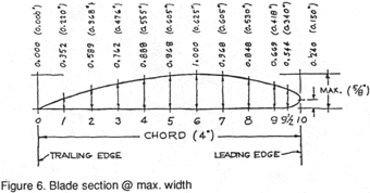
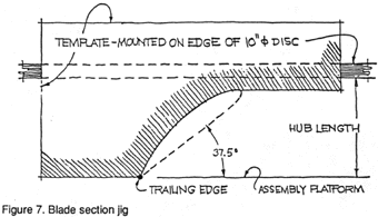
At this point, we can turn the propeller over and rasp off just the corners of the laminations on the back surface of the blades. Before we can proceed with the final shaping of the blade sections, we need to make one more template: that of the blade-section at maximum blade width. This will be an airfoil shape, whose heights ("ordinates") above the straight-line face of the blade, at ten equally-spaced stations along the blade width or "chord", are shown first as percentages of the maximum blade thickness at this radius (in our case, 5/8 inch (16 mm) and 5 inches (127 mm), respectively, for a chord length of 4 inches (162 mm), and then as inches for our example. Thus, the next task is to carefully lay out this blade-section profile on a sheet of tough, thin cardboard and cut it to shape. The cardboard is then trimmed to the form shown in the figure and mounted perpendicularly around the edge of a 10 inch (254 mm) diameter disk of 1/2 inch (12.7 mm) plywood, which fits over the 3/4 inch (19 mm) dowel on the assembly platform. With the propeller helicoidal surface face down on the platform, use this jig to check your profiling of the back of each blade at the 5 inch (127 mm) radius. When this is done, rasp and file off the rest of the blade surfaces, using the radial lines of the plywood laminations as guides to produce a smooth, fair surface based on this key section. The tip of the blades should be trimmed to about a 1/8 inch (3 mm) radius. The final step is to form the curved part of the blade face at the leading edge, and then the surface of the entire propeller is smoothed off with progressively finer grades of sandpaper. The last step is to paint the propeller with two coats of epoxy, sanding after each to end with a very smooth finish. Be sure to epoxy the inside of the bore for the propeller shaft, too. The propeller can be secured to the propeller shaft by means of a roll pin through the hub and shaft. If desired, a tail-cone of laminated plywood can be epoxied behind the hub. If the propeller becomes damaged in use, it may be easily repaired by cutting out the affected area to reach sound material, and filling in the void to the original profile and contour with a stiff paste of epoxy and fine sawdust. A subsequent filing and sanding to the original form completes the repair. 
|

Notes: 1. According to DeLong, an "average" person can sustain an output of about 0.225 hp (170 watts) over a one-hour period, with near maximum efficiency at a pedal speed of 60 rpm. Assuming a mechanical efficiency of 0.9 and a gear ration of 1:4, this results in 0.2 hp (150 watts) and 240 rpm at the propeller. The Troost B.3.35 model is a high-efficiency pattern with good acceleration characteristics, suitable for an all-weather cruising boat. As embodied here it differs from the original with the elimination of the 15-degrees-aft blade rake, and a slightly thicker blade section. See: Fred DeLong, DeLong's Guide to Bicycles and Bicycling, Radnor, PA: Chilton Book Co., 1978; and L.Troost, "Open Water Test Series with Modern Propeller Forms", Newcastle, G.B.: Transactions ofthe North-East Coast Institution of Naval Architects, 1950-51. For an accessible introduction to the details of empirical propeller design, see Dave Gerr, Propeller Handbook, Camden, ME, USA: Internat'l Marine Publishing Co., 1989. 2. To give a developed-area ratio of 0.35. The developed-area ratio (DAR) is the true area of the blade (not the projected area) times the number of blades; divided by the disc area of the propeller, or Philip Thiel 4720 7th Avenue NE Seattle WA 98105 USA Philip Thiel has taught naval architecture at M.I.T., and architecture at Berkeley and the University of Washington in Seattle. His interest is in facilitating the do-it-yourself construction of pedal-powered cruising craft. |
 |
© 2001-2013 by Philip Thiel Seattle WA USA |